4.
Development of applications (1)
4.1 How to modify if we want to use
another serial port?
A: The driver is ready on the MYD-Y6UL/6ULL
development board. We only need to modify dts file. The specific pin depends on
practical case.
-
Open
the kernel source code file “/arch/arm/boot/dts/myb-y6ull-14x14.dts”
UART: take the example of adding UART3. Please
note to delete the 2 lines about UART3 in original dts file “pincrl_uart2”
because there is only 1 usage mode for 1 pin.
-
In “myb-y6ull-14x14.dts”,
add UART3 referring to existing UART.
pinctrl_uart3: uart3grp
{ fsl,pins = <
MX6UL_PAD_UART3_TX_DATA__UART3_DCE_TX 0x1b0b1
MX6UL_PAD_UART3_RX_DATA__UART3_DCE_RX 0x1b0b1
>;
};
……..
&uart3 { pinctrl-names
= "default";
pinctrl-0 =
<&pinctrl_uart3>;
status =
"okay";
};
4.2 How to debug I2C?
A: Determine which pin to use according to the hardware
design. Open the kernel source code file “/arch/arm/boot/dts/myb-y6ull-14x14.dts”.
The codes for I2C1 and I2C2 are provided in “myb-y6ull-14x14.dts”.
So here we take the example of I2C3. Disable fec2 because I2C3 uses fec2.
&i2c3 { clock-frequency = <100000>;
pinctrl-names = "default";
pinctrl-0 =
<&pinctrl_i2c3>;
status =
"okay";
};
……….
pinctrl_i2c3:
i2c3grp { fsl,pins
= < MX6UL_PAD_ENET2_RX_DATA0__I2C3_SCL 0x4001b8b0 MX6UL_PAD_ENET2_RX_DATA1__I2C3_SDA 0x4001b8b0
}
4.3 How to debug SPI?
A: Determine which pin to use according to the hardware
design. Open the kernel source code file “/arch/arm/boot/dts/myb-y6ull-14x14.dts”.
Modify dts file and the following example codes.
Which SPI to use and pin configuration depends on practical demand.
Enable spi_dev in “make menuconfig”.
Directory: SPI SUPPORT/User mode SPI device driver
support
pinctrl_ecspi1:
ecspi1grp {
fsl,pins
= <
MX6UL_PAD_CSI_DATA07__ECSPI1_MISO
0x100b1
MX6UL_PAD_CSI_DATA06__ECSPI1_MOSI
0x100b1
MX6UL_PAD_CSI_DATA04__ECSPI1_SCLK
0x100b1
>;
};
pinctrl_ecspi1_cs:
ecspi1cs {
fsl,pins
= <
MX6UL_PAD_CSI_DATA05__GPIO4_IO26 0x80000000
>;
};
……..
&ecspi1 {
compatible =
"fsl,imx6ul-ecspi";
fsl,spi-num-chipselects
= <1>;
cs-gpios =
<&gpio4 26 0>;
pinctrl-names =
"default";
pinctrl-0 =
<&pinctrl_ecspi1 &pinctrl_ecspi1_cs>;
status =
"okay";
spidev@0x00{
#address-cellss=<1>;
#size-cells=<1>;
compatible =
"spidev";
spi-max-frequency
= <8000000>;
reg =
<0>;
};
};
4.4 How to debug RS485?
A: Determine which pin to use according to the hardware
design. Open the kernel source code file “/arch/arm/boot/dts/myb-y6ull-14x14.dts”.
Example code:
pinctrl_uart3:
uart3grp {
fsl,pins
= <
MX6UL_PAD_UART3_RX_DATA__UART3_DCE_RX 0x1b0b1
MX6UL_PAD_UART3_TX_DATA__UART3_DCE_TX 0x1b0b1
/* MX6UL_PAD_UART1_CTS_B__GPIO1_IO18 0x1b0b1 RS485 RE/DE */
>;
};
……………………
&uart3 {
pinctrl-names =
"default";
pinctrl-0 =
<&pinctrl_uart3>;
fsl, rs485-gpio-txen
= <&gpio1 18 GPIO_ACTIVE_HIGH>;
linux,rs485-enable-at-boot-time;
status =
"okay";
};
4.5 How to debug ADC?
A: Determine which pin to use according to the hardware
design. Open the kernel source code file “/arch/arm/boot/dts/myb-y6ull-14x14.dts”.
regulators {
compatible =
"simple-bus";
#address-cells
= <1>;
#size-cells
= <0>;
reg_can_3v3:
regulator@0 {
compatible
= "regulator-fixed";
reg =
<0>;
regulator-name
= "can-3v3";
regulator-min-microvolt
= <3300000>;
regulator-max-microvolt
= <3300000>;
};
reg_vref_3v3: regulator@3 {
compatible =
"regulator-fixed";
regulator-name
= "vref-3v3";
regulator-min-microvolt =
<3300000>;
regulator-max-microvolt =
<3300000>;
}
}
pinctrl_adc1: adc1grp {
fsl,pins = <
MX6UL_PAD_GPIO1_IO01__GPIO1_IO01 0xb0
>;
};
…..
&adc1 {
pinctrl-names =
"default";
pinctrl-0 =
<&pinctrl_adc1>;
num-channels = <1>;
vref-supply =
<®_vref_3v3>;
status =
"okay";
};
Enable iio and
vf610_adc through “make menuconfig”, then compile to generate new kernel and
dtb file.
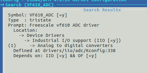
4-5-1
Enable VF610_ADC in kernel
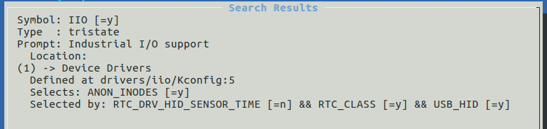
4-5-2
Enable IIO in kernel
Then read value and set parameters from
directories including “/sys/bus/iio/devices/iio\:device0/”
4.6 How to debug GPIO?
A: Determine which pin to use according to the
hardware design. Open the kernel source code file “/arch/arm/boot/dts/myb-y6ull-14x14.dts”.
GPIO: set LCD_DATA0 as GPIO.
&iomuxc {
pinctrl-names =
"default";
pinctrl-0 =
<&pinctrl_hog_1>;
imx6ul-evk {
pinctrl_hog_1:
hoggrp-1 {
fsl,pins
= <
MX6UL_PAD_UART1_RTS_B__GPIO1_IO19 0x17059 /* SD1 CD */
MX6UL_PAD_JTAG_MOD__GPIO1_IO10 0x17059 /* WiFi module power */
MX6UL_PAD_NAND_CE1_B__GPIO4_IO14 0x17059 /* LTE Reset */
MX6UL_PAD_GPIO1_IO00__ANATOP_OTG1_ID 0x17059 /* USB OTG1 ID */
MX6UL_PAD_GPIO1_IO09__GPIO1_IO09 0x1b0b0 /* LCD_DISP */
MX6UL_PAD_GPIO1_IO02__GPIO1_IO02 0x10b1
MX6UL_PAD_LCD_DATA00__GPIO3_IO05 0x1b0b0 (Set LCD_DATA0 as GPIO)
……
&lcdif {
pinctrl-names =
"default";
pinctrl-0 =
<&pinctrl_lcdif_dat_16bits
&pinctrl_lcdif_ctrl
&pinctrl_lcdif_reset>;
display =
<&display0>;
status =
"disabled"; (Disable previous
usage of LCD_DATA0)
After above modification to dts file, load the
tool chain to compile.
|


