4K
resolution refers to a horizontal display
resolution of
approximately 4,000 pixels. Digital
television and digital
cinematography commonly
use several different 4K resolutions. In television and consumer media, 3840 × 2160 (4K UHD) is the dominant 4K standard, whereas
the movie projection industry uses 4096 × 2160 (DCI 4K).
|
Resolution
|
Horizontal x Vertical
pixels
|
Other names
|
Devices
|
|
DCI 4K
|
4,096 x 2160
|
4K
|
Projectors
|
|
4K UHD
|
3,840 x 2,160
|
4K, Ultra HD, Ultra-High Definition
|
TVs, monitors
|
|
2K
|
2,048 x 1,080
|
none
|
Projectors
|
|
1080p
|
1,920 x 1,080
|
Full HD, FHD, HD, High Definition
|
TVs, monitors
|
|
720p
|
1,280 x 720
|
HD, High Definition
|
TVs
|
As
image sizes bit depth grow larger, software image processing capabilities become
limited. So, hardware is needed to take place. FPGA (Field-Programmable Gate
Array), leveraging hardware representations of algorithms, is often used as
implementation platforms for real-time image processing applications.
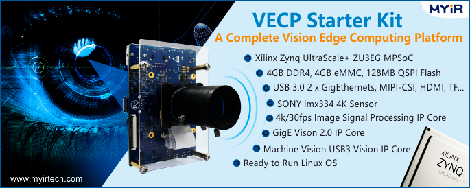
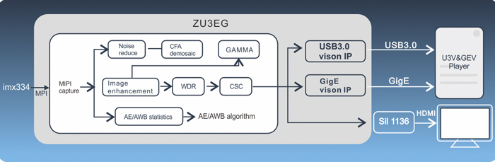
The VECP Starter Kit is a
complete Vision Edge Computing Platform to provide an excellent image
processing solution based on Xilinx Zynq UltraScale+ ZU3EG MPSoC which
features a 1.2 GHz quad-core ARM
Cortex-A53 64-bit application processor, a 600MHz
dual-core real-time ARM
Cortex-R5 processor, a Mali400 embedded GPU and rich
FPGA fabric. The VECP main board MYD-CZU3EG-ISP has a SONY imx334 4K
Sensor and can acquire 4k images through diversified image output interfaces
including HDMI, Gigabit Ethernet and USB 3.0. Below let’s see how to use FPGA
board to capture 4k video images.
1. Preparations
Copy the image file and camera testing file
provided by MYIR to the TF card. Install the image acquisition software OCT SDK
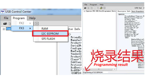
tool provided in the product disk. Meanwhile, download FX3 SDK tool from
cypress website for firmware programming. (Pleaser refer to the MYD-CZU3EG-ISP documentations
to get detailed file path).
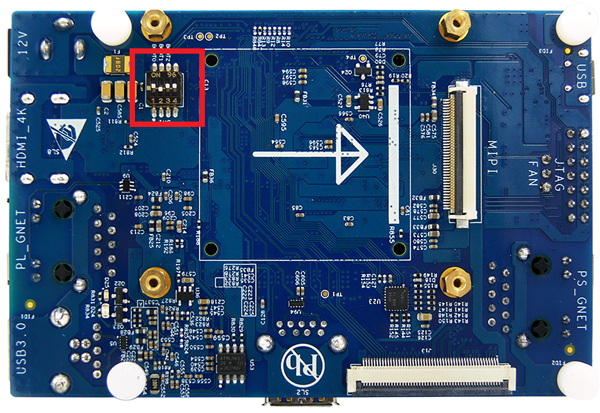
2. Operation
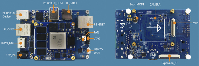
1) Set the MYD-CZU3EG-ISP board boot mode switch SW1: Pin 1 - OFF, Pin 2 - ON, Pin 3 - OFF, Pin 4 – ON
The board will boot from TF card.
2) Insert the TF card and connect the UART to set 115200 baud rates, then
power on the development board.
3) The MYD-CZU3EG-ISP board will entry Ramdisk file system and get into Linux
command line:
Welcome to myir board
myir login: root
[root@myir ~]#
4) Open the OCT SDK tool and select “OCAM
Technology” as shown in below image. Right click and select “Connect>Window:1”
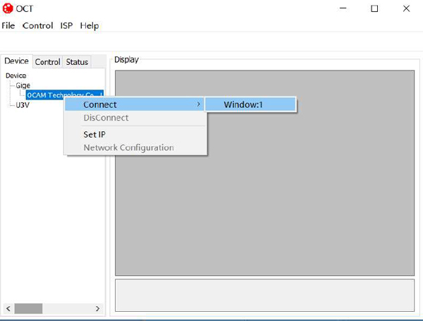
Move
the cursor to the right video zone. Right click and select “Start”.
5) Send control command, set Gige (Gigabit Ethernet interface) as the output video
source to be 1 and select “PS VDMA” to be the output video source.
[root@myir
~]# cd /mnt/mmcblk1p1/
[root@myir
mmcblk1p1]# ./setispcmd 81 01 12 00 01 00 02 ff
6) Capture image and input below command, an image file rgb888 will be
created.
[root@myir mmcblk1p1]# ./ispcaptest
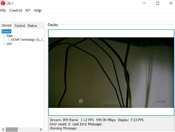
7) Display capturing image
[root@myir mmcblk1p1]# cat rgb888 >/dev/fb0
8) The OCT tool will display the captured image.
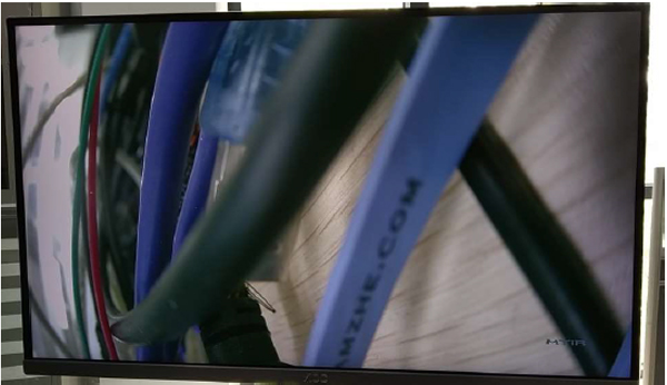
3. HDMI Output Display
If you want
to use HDMI interface to output and display 4k image, please input below
command, the image will be shown as following.
[root@myir ~]# cd /mnt/mmcblk1p1/
[root@myir mmcblk1p1]# ./setispcmd 81 01 12 00 01 00 01 ff
[root@myir mmcblk1p1]# ./ispcaptest
[root@myir mmcblk1p1]# cat rgb888 >/dev/fb0
4. USB Output Display
If you want to use
USB to output and display image, please follow the file “MYD-CZU3EG-ISP
function description and FPGA
compilation” to create BOOT.bin which includes the USB
output display function. Replace the BOOT.bin file in the
TF card, the image
will be shown as following.
[root@myir ~]# cd /mnt/mmcblk1p1/
[root@myir mmcblk1p1]# ./setispcmd 81 01 12 00 01 00 04 ff
[root@myir mmcblk1p1]# ./ispcaptest
[root@myir mmcblk1p1]# cat rgb888 >/dev/fb0
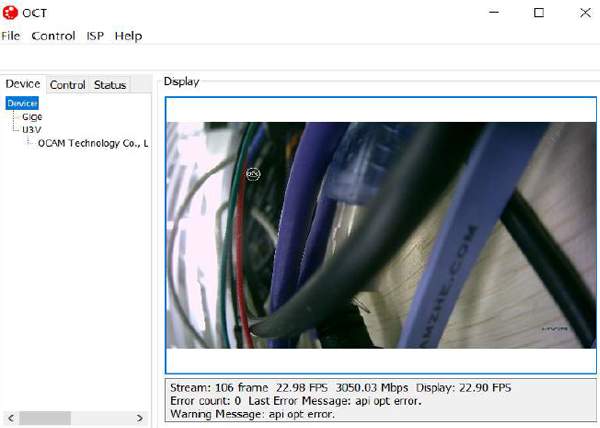
Image output from HDMI or USB 3.0 YouTube Video Demo
5. HDMI Display QT Interface
Set the
MYD-CZU3EG-ISP board boot mode switch SW1: Pin 1 - OFF, Pin 2 - ON, Pin 3 - OFF, Pin 4 – ON
The board will boot from TF card.
Insert the TF card and connect the UART to
set 115200 baud rates, then power on the development board. The MYD-CZU3EG-ISP board will entry Ramdisk
file system and get into Linux command line. Input command to start updating.
Welcome to
myir board
myir login: root
[root@myir ~]#/updatesys.sh /mnt/mmcblk1p1
The script
will program the BOOT.bin, devicetree.dtb and Image to QSPI-Flash and the
rootfs.tar to eMMC. When finished programming, please set the MYD-CZU3EG-ISP board boot mode switch SW1: Pin 1 – ON, Pin 2 – OFF, Pin 3 – ON, Pin 4 – ON
The board will boot from QSPI Flash. Power on again to start programming rootfs
file system. Input below command:
Welcome to myir board
myir login: root
[root@myir ~]# /mnt/mmcblk1p1/setispcmd 81 01 12 00 01 00 01 ff
[root@myir ~]# /usr/lib/qt/examples/widgets/painting/deform/deform
6. Video Source
Selection Command Instruction
Please
refer to below table to check the ISP video source control instruction set.
Please also refer to the file “MYD-CZU3EG-ISP Board Image Control Instruction
Manual” provided by MYIR.
|
ISP Video Source Control
Instruction Set
|
|
Command
Set
|
Command
|
Command
Packet
|
Comments
|
|
PL
Output
Port Video
Source Select
|
PL
Video
Output
Select
|
81
01 12 00 01 00 0Y ff
|
Bit0, 1 and 2 of Y are
respectively indicating HDMI, GigE and U3V output video source selection:
0 – select PL ISP output video;
1 – select PS VDMA output video
|
|