This evaluation experience is brought by developer “HonestQiao” from ElecFans. Let's take a look at how he implemented the monitoring platform through MYIR's i.MX 6ULL based MYD-Y6ULX-V2 development board.
MYD-Y6ULX-V2 Development Board
1. Evaluation Planning
The MYD-Y6ULX-V2 development board has a SIM card slot. The plan is to use it to make a remote monitoring platform.
The board itself does not come with an LTE module, it requires an LTE module with a Mini PCI-E interface to be able to use 4G networks, and which supports Quectel’s EC20 model. Without this LTE module on hand, the second option is to use a wired network for data transmission. The full image file of this board provides support for USB camera through V4L, and can be used directly by plugging in the USB camera module. The evaluation plan is as follows:
- Use the MYD-Y6ULX-V2 development board to provide camera monitoring data;
- Use OLED to present the device load, IP address and service information of the development board;
- Use PyQT5 to develop the monitor display interface;
- Use opencv for face recognition detection.
2. Hardware Preparation
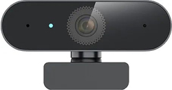
1) USB Camera
I use a Hikvision USB camera, and other USB cameras work just as well.
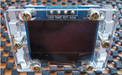
2) SSD1306 OLED
The MYD-Y6ULX-V2 development board supports IIC and SPI communications. I just have a SSD1306 OLED which supports IIC communication.
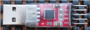
3) USB2TTL
We need to do some basic setup using a serial port connection when we start to use the MYD-Y6ULX-V2 development board.
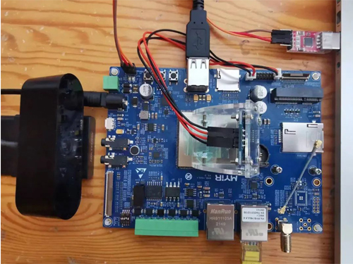
4) MYD-Y6ULX-V2 Development Board
Connect the above devices to the MYD-Y6ULX-V2 development board as follows.
3. Burning Image
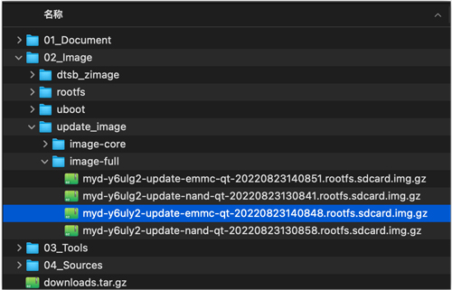
The MYD-Y6ULX-V2 development board is preloaded with system image, but we can update with the latest version ourselves if needed. According to the manual, select the following image and set the boot mode, start burning and updating.
1) Image Type
Full image for eMMC boot
2) Burning Mode
First extract the above image, then use the official Win32 Disk Imager burn to the SD card, and then connect to the development board.
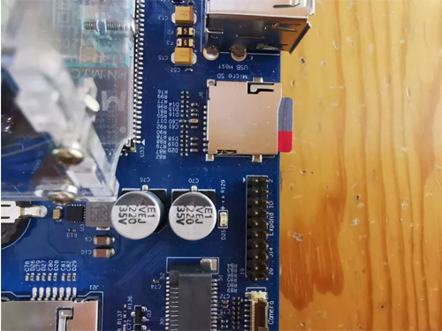
3) Dip Switch
The MYD-Y6ULX-V2 development board used is the eMMC version, so select the appropriate startup mode when updating, as shown below.
|
Boot Device
|
SW1
|
Remark
|
|
eMMC
|
OFF/OFF/ON/OFF
|
|
|
Nand Flash
|
OFF/ON/ON/OFF
|
|
|
TF Card (Board with eMMC version)
|
ON/ON/ON/OFF
|
|
|
TF Card (Board with Nand Flash version)
|
ON/OFF/ON/OFF
|
|
|
USB Download
|
X/X/OFF/ON
|
USB_OTG1 download image
|
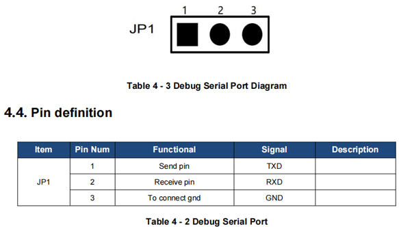
4) Connect the Debugging Serial Port
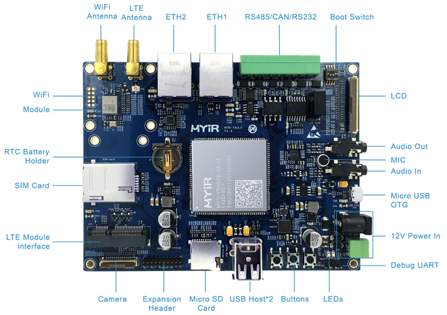
Referring to the interface distribution of the development board, USB2TTL is used to connect the debugging serial port of the development board to the computer.
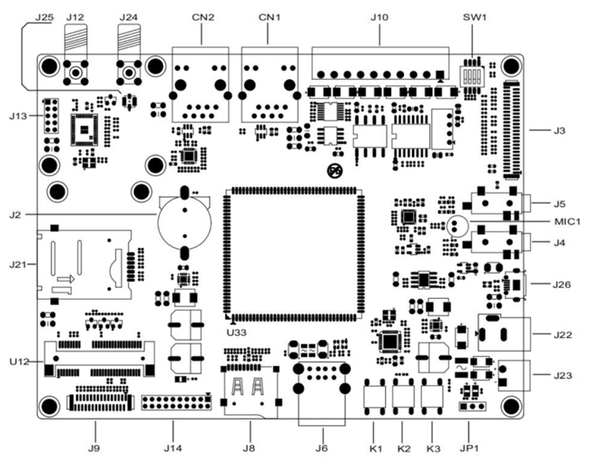
MYD-Y6ULX-V2 Interface Layout
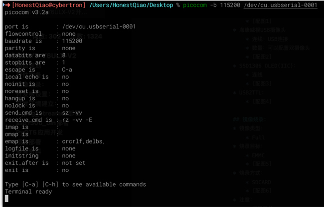
On the computer side, use the serial port terminal tool to connect:
Windows can use Putty or mobaxterm. Linux and macOS can use minicom or picocom. I'm using macOS, so I use picocom to connect.
5) Burning
When the development board is installed off, insert the SD card, power on and start up again, and the development board will start automatically, enter the state of brushing, and output a message indicating that the upgrade is under way. The upgrade will take a while, please be patient.
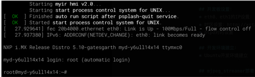
6) Verification
After the update is successful, power off the device, set the DIP switch back to the eMMC startup mode, and restart the device. The following startup message will be displayed: "NXP i.MX Release Distro 5.10-gatesgarth" indicates the update to the current system.
4. Development Board Setup
After the update is completed, some basic Settings need to be carried out on the development board to facilitate the subsequent further operations.
1) IP Settings for eth0 and eth1
Refer to: General Network Configuration
To modify the file using vi: /etc/systemd/network/10-static-eth0.network
To modify the file using vi: /etc/systemd/network/11-static-eth1.network
The following is an example of a static configuration:
[Match]
Name=eth0
[Network]
Address=192.168.1.177/24
Gateway=192.168.1.1
DNS=192.168.1.1
The following is an example of dynamic configuration:
[Match]
Name=eth0
[Network]
DHCP=yes
EOF
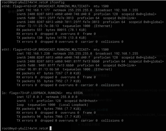
After the configuration, we can restart the network service and view the result:
service systemd-networkd restart
Ifconfig
2) Time Zone Settings
Reference: ntpd clock synchronization service
Modify using vi: /etc/sysconfig/clock
ZONE="Asia/Shanghai"
UTC=true
ARC=false
cp /usr/share/zoneinfo/Asia/Shanghai /etc/localtime
3) Ntpd Time Settings
Reference: ntpd clock synchronization service
Modify using vi: /etc/sysconfig/ntpd
# Drop root to id 'ntp:ntp' by default.
OPTIONS="-u ntp:ntp -p /var/run/ntpd.pid"
# Set to 'yes' to sync hw clock after successful ntpdate
SYNC_HWCLOCK=yes #make no into yes; BIOS的时间也会跟着修改
# Additional options for ntpdate
NTPDATE_OPTIONS=""
Modify using vi: /etc/ntp.conf
restrict default kod nomodify notrap nopeer noquery
# restrict -6 default kod nomodify notrap nopeer noquery #针对ipv6设置
# 允许本地所有操作
restrict 127.0.0.1
#restrict -6 ::1
# 允许的局域网络段或单独ip
restrict 10.0.0.0 mask 255.0.0.0 nomodify motrap
restrict 192.168.0.0 mask 255.255.255.0 nomodify motrap
restrict 192.168.1.123 mask 255.255.255.255 nomodify motrap
# 使用上层的internet ntp服务器
server cn.pool.ntp.org prefer
server 0.asia.pool.ntp.org
server 3.asia.pool.ntp.org
server 0.centos.pool.ntp.org iburst
# 如果无法与上层ntp server通信以本地时间为标准时间
server 127.127.1.0 # local clock
fudge 127.127.1.0 stratum 10
# 计算本ntp server 与上层ntpserver的频率误差
driftfile /var/lib/ntp/drift
# Key file containing the keys and key identifiers used when operating
# with symmetric key cryptography.
keys /etc/ntp/keys
#日志文件
logfile /var/log/ntp.log
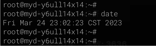
Restart the service to take effect:
service ntpd restart
Date
View the results:
4) Remote Connection
Once all of the above Settings are complete, we can connect to the development board from another computer using an ssh remote connection.
First, on the development board, set a password for the root user:
passwd root
Then, on another computer, use the ssh tool to connect remotely:
On Windows, we can use Putty or mobaxterm. On Linux and macOS, we can use the ssh command.
ssh root@192.168.1.177
# 出现下一行提示附后,就可以输入命令了:
root@myd-y6ull14x14:~#
root@myd-y6ull14x14:~# uname -a
Linux myd-y6ull14x14 5.10.9-1.0.0+g062cea228 #1 SMP PREEMPT Fri Aug 12 02:04:17 UTC 2022 armv7l armv7l armv7l GNU/Linux
5. Setting up the Development Environment
MYIR has provided detailed guidance for the establishment of development environment for MYD-Y6ULX-V2 development board, we can refer to "MYD-Y6ULX Linux System Development Guide" to complete the required work.
The development environment needs to be built in an Ubuntu environment, not on the development board's own system.
1) Setup of Ubuntu Development Environment
From the development board SDK page, download the image.
First install the base kit and build the working directory:
sudo apt-get install gawk wget git-core diffstat unzip texinfo gcc-multilib build-essential chrpath socat cpio python3 python3-pip python3-pexpect xz-utils debianutils iputils-ping python3-git python3-jinja2 libegl1-mesa libsdl1.2-dev
mkdir -p ~/MYD-Y6ULX-devel
export DEV_ROOT=~/MYD-Y6ULX-devel
sudo mkdir /media/cdimage
sudo mount -o loop ~/Downloads/MYD-Y6ULX_L5.10.9_20220826.iso /media/cdimage
cp -r /mnt/cdimage/02_Images $DEV_ROOT/
cp -r /mnt/cdimage/03_Tools $DEV_ROOT/
cp -r /mnt/cdimage/04_Sources $DEV_ROOT/
2) Install compile chain
According to the instructions in the manual, use the application toolchain of the full system in order to cross-compile the application.
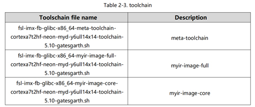
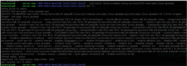
cd $DEV_ROOT/03_Tools/Tools_chain/
bash fsl-imx-fb-glibc-x86_64-myir-image-full-cortexa7t2hf-neon-myd-y6ull14x14-toolchain-5.10-gatesgarth.sh
. /opt/test5.10/environment-setup-cortexa7t2hf-neon-poky-linux-gnueabi
$CC -v
Prompt for installing the compilation toolchain: Install it in /opt/test5.10
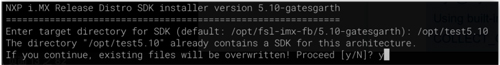
Verification after installation:
6. mjpg_streamer Deployment
Since we need to use the camera and provide monitoring data externally, mjpg_streamer is a good choice.
mjpg_streamer branch version: https://github.com/jacksonliam/mjpg-streamer
Download link: https://github.com/jacksonliam/mjpg-streamer/archive/refs/heads/master.zip
1) Cross-compile:
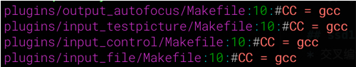
We can use the CC settings of the cross-compiler environment, but we need to comment out the gcc Settings of the mjpg_streamer source code, as follows.
cd mjpg-streamer/mjpg-streamer-experimental
find -name "Makefile" -exec sed -i "s/CC = gcc/#CC = gcc/g" {} \;
grep -rn 'CC = gcc' *
make clean
make
After the CC configuration is modified, use grep to obtain the following output:
When the compilation is complete, the result is as follows:
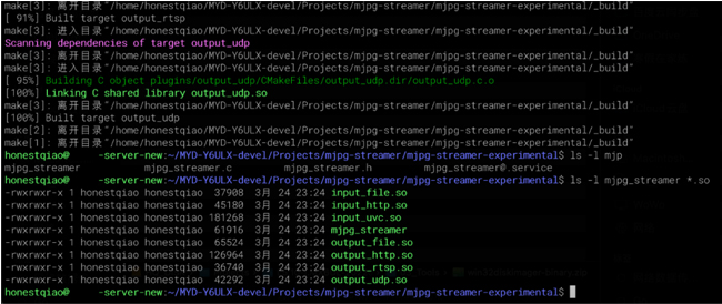
2) Deploy with so file
Copy the above files to the development board using scp.
ssh root@192.168.1.177 "mkdir ~/mjpeg_server/"
scp mjpg_streamer root@192.168.1.177:~/mjpeg_server/
scp *.so root@192.168.1.177:~/mjpeg_server/
3) mjpeg_streamer test
With mjpg_streamer deployed on the development board, we can connect to the development board remotely for testing.
Viewing camera device:
View device instruction: v4l2-ctl --list-devices
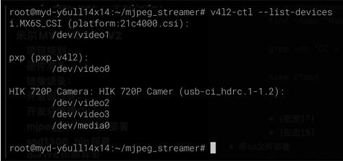
As can be seen from the figure above, the connected USB Camera HIK 720P Camera is identified, and the corresponding first device address /dev/video2 can be called by mjpg_streamer.
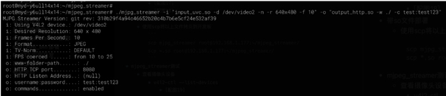
4) Launch the mjpg_streamer test
cd ~/mjpeg_server
./mjpg_streamer -i "input_uvc.so -d /dev/video2 -n -r 640x480 -f 10" -o "output_http.so -w ./"
mjpg_streamer on default startup can be accessed arbitrarily, which may not be secure. But we can set an access password by using “-c username: password”, as shown in the following figure:
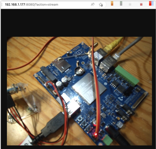
5) Access test
Now on other computers, we can access the camera data stream provided on the development board directly through the browser.
In my environment, access address to http://192.168.1.177:8080/? action=stream
7. ssd1306_bin Deployment
The SSD1306 OLED I use communicates through IIC, and I have used ssd1306 tool under Linux environment before.
After trial, this tool can be compiled and used by the MYD-Y6ULX-V2 development board compilation tool chain.
Download link: https://github.com/armlabs/ssd1306_linux/archive/refs/heads/master.zip
1) Cross-compile:
Modify the configuration file Makefile as follows:
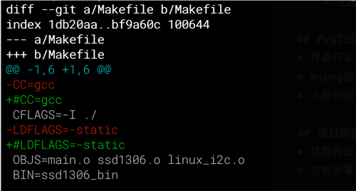
After the modification is complete, compile the file. After the compilation is complete, deploy the ssd1306_bin file.
make
ls -l ssd1306_bin
# 部署文件到开发板
scp ssd1306_bin root@192.168.1.177:~/mjpeg_server/
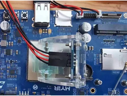
1) Hardware connection
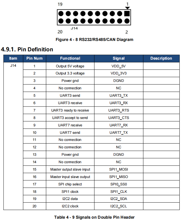
Refer to the instructions in the ”MYD-Y6ULX-V2 Hardware User`s Guide” to connect the hardware. The OLED I use uses VDD_5V, DGND, I2C2_SCL, I2C2_SDA. Be sure to pay attention to the voltage of the OLED you are using, some can only use 3.3V.
2) OLED display test
After the above hardware connection is complete, we can remotely connect to the development board for testing.
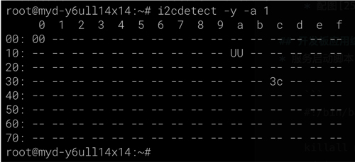
Check whether the OLED device is successfully connected to the hardware. Usually the IIC address is 3c:
i2cdetect -y -a 1
Then, perform the display test:
cd ~/mjpeg_server
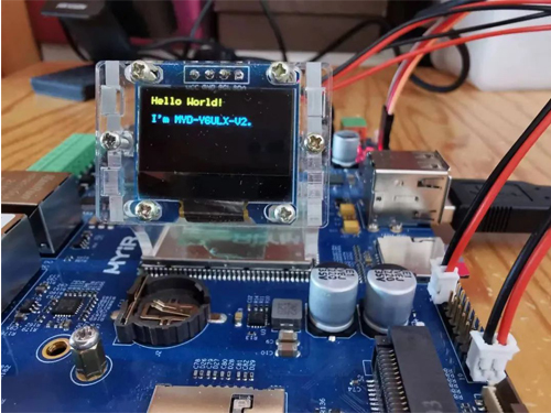
./ssd1306_bin -n 1 -I 128x64
./ssd1306_bin -n 1 -c
./ssd1306_bin -n 1 -r 0
./ssd1306_bin -n 1 -x 0 -y -0 -m "Hello World!\n\nI'm MYD-Y6ULX-V2."
8. Development Board Application Comprehensive Deployment
Completion of the above two steps, the foundation work for the development board section is complete, we can write a startup script for control, as follows:
In order to secure access, I have set the user name and password for access in the script, which you can also modify according to your actual needs.
And the following operations need to be remotely connected to the development board.
1) Service startup script:~/mjpeg_server/mjpeg_server_start.sh
#!/bin/bash
cd "${0%/*}"
killall mjpg_streamer >/dev/nul 2>&1
device=$(v4l2-ctl --list-devices | grep 'Camera' -A1 | grep /dev/video | head -1 | awk '{print $NF}')
./mjpg_streamer -i "input_uvc.so -d $device -n -r 640x480 -f 10" -o "output_http.so -w ./ -c test:test123" &
./ssd1306_bin -n 1 -I 128x64
./ssd1306_bin -n 1 -r 0
let count=0
while true
do
nowdate="$(date '+%Y-%m-%d %H:%M:%S')"
load="$(w | head -1 | sed -e 's/^.*average: //' | cut -d ',' -f 1)"
temp=$(echo "scale=1;$(cat /sys/devices/virtual/thermal/thermal_zone0/temp)/1000" | bc)
ipstr=" ${nowdate}\n L:${load} T:${temp}"
if [[ $count -gt 0 ]];then
./ssd1306_bin -n 1 -x 0 -y 0 -m "${ipstr}"
else
./ssd1306_bin -n 1 -c
ipstr="${ipstr}\n**-*-IP Address-*-**"
i=0
for ip in $(ip addr show | grep -v "127.0.0.1" | awk -F'[ /]+' '{if($0 ~ / inet /) print $3;}')
do
let i=i+1
ipstr="${ipstr}\nIP${i}: ${ip}"
done
ipstr="${ipstr}\nSRV: ip:8080/?action"
ipstr="${ipstr}\n =stream"
echo -e "${ipstr}"
./ssd1306_bin -n 1 -x 0 -y 0 -m "${ipstr}"
fi
let count=count+1
if [[ $count -gt 15 ]];then
let count=0
fi
sleep 1
done
2) Start up:
Set the permissions to start the script.
chmod u+x /home/root/mjpeg_server/mjpeg_server_start.sh
Start the above script from /etc/rc.local, and add the following command to /etc/rc.local
screen -S mjpeg_server /home/root/mjpeg_server/mjpeg_server_start.sh
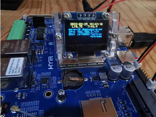
After the configuration is complete, the development board can be restarted, and the OLED display will display the corresponding information:
Then on the computer, open the previous access address, to test.
9. PyQT5 Application Development
The full environment of MYD-Y6ULX-V2 development board supports application development using QT5, but in actual use, we need to cooperate with the screen. I don't have a screen on hand, so I do this step on a PC and use PyQT5 for development. Specific work to be done is as follows:
- Operation interface development
- mjpeg stream read display
- Face recognition
Face recognition part, I have referred to opencv quick start of face detection and recognition
Related to the specific source code are as follows for reference.
from PyQt5 import QtWidgets
from PyQt5.QtGui import QImage, QPixmap, QKeySequence
from PyQt5.QtCore import QThread
import sys, cv2, threading, random, signal
import numpy as np
import socket
import time, datetime
import requests
from requests.auth import HTTPBasicAuth
# 0-摄像头 1-socket 2-from remote
CAMERA_SOURCE = 2
CAMERA_LOCAL_INDEX = 0 # 如果使用本地摄像头,则表示其videoN的N
CAMERA_SOCKET_PORT = 8888 # 如果视同socket,设置端口
# CAMERA_REMOTE_URL = "http://192.168.1.15:8080/live.mjpg"
CAMERA_REMOTE_URL = "http://192.168.1.177:8080/?action=stream"
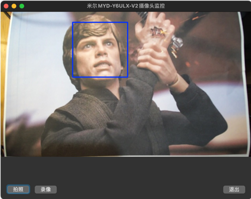
CAMERA_SOURCE_NAME = ["USB摄像头", "网络图像流", "米尔MYD-Y6ULX-V2摄像头监控"]
AUTH_CONFIG = {"user":"test","pass":"test123"}
FACE_DETECTION = True
if FACE_DETECTION == True:
# https://blog.csdn.net/FontThrone/article/details/105314973
# https://github.com/FontTian/DS-Exhibitio
face_cascade = cv2.CascadeClassifier('haarcascade_frontalface_default.xml')
face_cascade.load('./haarcascades/haarcascade_frontalface_default.xml')
face_box_colors = [
(255, 0, 0),
(0, 255, 0),
(0, 255, 0),
(255, 255, 0),
(255, 0, 255),
(0, 255, 255),
(255, 128, 128),
(128, 255, 128),
(128, 255, 128),
(255, 255, 128),
(255, 128, 255),
(128, 255, 255)
]
# 应用定义
app = QtWidgets.QApplication(sys.argv)
window_w, window_h = 640, 480 # 窗口宽度和高度
scale = 0.58 # 视频信息宽高比
# 界面定义
Form = QtWidgets.QWidget()
Form.setWindowTitle(CAMERA_SOURCE_NAME[CAMERA_SOURCE])
Form.resize(window_w, window_h)
# 窗口大小改变时自动调整按钮
def windowResize(self):
global window_w, window_h, scale
window_w = Form.width() # 窗口宽度
window_h = Form.height() # 窗口高度
label.setGeometry(0,0, window_w, int(window_w*scale)) # 调整 QLabel 尺寸
btn1.setGeometry(10, window_h-40,70,30) # 调整按钮位置
btn2.setGeometry(80, window_h-40,70,30) # 调整按钮位置
btn3.setGeometry(window_w - 80, window_h-40,70,30) # 调整按钮位置
Form.resizeEvent = windowResize # 设置窗口大小改变时触发
# 关闭应用时的处理
ocv = True # 设置是否处理视频
def closeOpenCV(self):
global ocv, output
ocv = False # 关闭窗口时,停止处理视频
print("关闭程序")
try:
output.release() # 关闭窗口时,释放视频处理资源
except:
pass
Form.closeEvent = closeOpenCV # 窗口关闭时触发
label = QtWidgets.QLabel(Form)
label.setGeometry(0,0, window_w, int(window_w*scale)) # 设置 QLabel 的位置和大小
# 存储文件时使用的文件名
def rename():
# return str(random.random()*10).replace('.','')
return datetime.datetime.now().strftime('%Y%m%d_%H%M%S')
photo = False # 按下拍照按钮时,设置处于拍照状态
# 按下拍照按钮时的处理
def takePhoto():
global photo
photo = True # 设定拍照状态为True
print("马上拍照")
btn1 = QtWidgets.QPushButton(Form)
btn1.setGeometry(10, window_h-40,70,30) # 设置拍照按钮的位置和大小
btn1.setText('拍照')
btn1.clicked.connect(takePhoto) # 按下拍照按钮时触发
fourcc = cv2.VideoWriter_fourcc(*'mp4v') # 设置视频中的存储格式
recorderType = False # 按下录像按钮时,设置处于录像状态
# 按下录像按钮时的处理
def recordVideo():
global recorderType, output
if recorderType == False:
# 如果按下按钮时没有在录像,则开始录像
# 设定存储的视频信息
output = cv2.VideoWriter(f'videos/{rename()}.mp4', fourcc, 20.0, (window_w, int(window_w*scale)))
recorderType = True # 设置正在录制状态
btn2.setGeometry(80, window_h-40,200,30) # 根据显示内容设置大小
btn2.setText('录像中,点击停止保存')
else:
# 如果按下按钮时正在在录像,则停止录像
output.release() # 释放视频存储资源
recorderType = False # 设置非录制状态
btn2.setGeometry(80, window_h-40,70,30) # 根据显示内容设置大小
btn2.setText('录像')
btn2 = QtWidgets.QPushButton(Form)
btn2.setGeometry(80, window_h-40,70,30) # 设置录像按钮的位置和大小
btn2.setText('录像')
btn2.clicked.connect(recordVideo) # 按下录像按钮时触发
# 按下退出按钮时的处理
def quitApp():
global video_server
print("退出程序")
closeOpenCV(False)
app = QtWidgets.QApplication.instance()
app.quit()
btn3 = QtWidgets.QPushButton(Form)
btn3.setGeometry(window_w-80, window_h-40,70,30) # 设置退出按钮的位置和大小
btn3.setText('退出')
btn3.clicked.connect(quitApp) # 按下退出按钮时触发
# 人脸识别处理
def face_detection_process(frame):
if FACE_DETECTION == True:
face_count = 0
gray = cv2.cvtColor(frame, cv2.COLOR_BGR2GRAY)
faces = face_cascade.detectMultiScale(gray, 1.3, 5)
for (x, y, w, h) in faces:
color = face_box_colors[face_count % len(face_box_colors)]
cv2.rectangle(frame, (x, y), (x + w, y + h), color, 2)
face_count+=1
# 此处省略本项目用不到的数百行...
# mjpeg数据流处理服务
def mjpeg_remote_server():
global window_w, window_h, scale, photo, output, recorderType, ocv
r = requests.get(CAMERA_REMOTE_URL, auth=HTTPBasicAuth(AUTH_CONFIG["user"], AUTH_CONFIG["pass"]), stream=True)
if(r.status_code != 200):
print("Received unexpected status code {}".format(r.status_code))
return
count = 0
is_first = False
recv_data_mjpeg = bytes()
for recv_data in r.iter_content(chunk_size=1024):
if not ocv:
break
count+=1
if count % 10000 == 1:
print("\trecv stream success")
recv_data_mjpeg += recv_data
a = recv_data_mjpeg.find(b'\xff\xd8')
b = recv_data_mjpeg.find(b'\xff\xd9')
if not (a != -1 and b != -1):
continue
mjpg_data_raw = recv_data_mjpeg[a:b+2]
recv_data_mjpeg = recv_data_mjpeg[b+2:]
mjpeg_data = np.frombuffer(mjpg_data_raw, 'uint8')
img = cv2.imdecode(mjpeg_data, cv2.IMREAD_COLOR)
# cv2.imshow('stream', img)
if not is_first:
is_first = True
sp = img.shape
sz1 = sp[0] #height(rows) of image
sz2 = sp[1] #width(colums) of image
sz3 = sp[2] #the pixels value is made up of three primary colors
print('网络图像: width=%d \theight=%d \tnumber=%d' % (sz1, sz2, sz3))
scale = sz1/sz2
frame = cv2.resize(img, (window_w, int(window_w*scale))) # 改变帧大小
if photo == True:
name = rename() # 设置文件名称
name_save = f'photos/{name}.jpg'
print("照片存储:%s" % name_save)
cv2.imwrite(name_save, frame) # 存储图片
photo = False # 拍照完,设置非拍照状态
if recorderType == True:
output.write(frame) # 按下录像按钮时,输出到存储文件
face_detection_process(frame)
frame = cv2.cvtColor(frame, cv2.COLOR_BGR2RGB) # 设置为 RGB
height, width, channel = frame.shape
bytesPerline = channel * width
img = QImage(frame, width, height, bytesPerline, QImage.Format_RGB888)
label.setPixmap(QPixmap.fromImage(img)) # 显示
if CAMERA_SOURCE == 2:
video_server = QThread()
video_server.run = mjpeg_remote_server
video_server.start()
Form.show()
sys.exit(app.exec_())
Set up the MJPEG video address of the development board, and then launch the python program above, we can see the following interface.
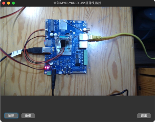
If a face appears in the interface, it will be automatically recognized.
|