|
|
|
 Products > Development Boards > MYD-C335X-V4 (TI AM335x) > MYD-C335X-V4 Development Board
 |
| |
 |
MYD-C335X-V4 Development Board |
- MYC-C335X-V4 as Controller Board
- Up to 1GHz TI AM335X Series ARM Cortex-A8 Processors
- 512MB DDR3 SDRAM (256MB compatible)
- 512MB Nand Flash (256MB compatible)
- Serial ports, 4 x USB Host, OTG, 2 x Gigabit Ethernet, CAN, RS485, TF, Audio
- Supports HDMI and LCD Display
- Optional 4.3- or 7- inch LCD Module
- Supports for Linux 4.1.18
|
|
|
|
| |
|
MYIR is a thrid party Partner of TI, welcome to use MYIR's TI series products!
We also offer ODM & OEM services, welcome your inquiry!
https://www.myirtech.com/tiseries.asp
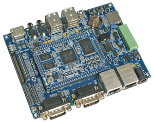
The MYD-C335X-V4 Development Board designed by MYIR is a high-performance
ARM Evaluation Module (EVM) using the MYC-C335X-V4 as the core
controller board. It is based on up to 1GHz Texas
Instruments (TI) Sitara AM335x family of ARM Cortex-A8 Microprocessors
(MPUs) that deliver high DMIPs at a low cost while also delivering optional 3D
graphics acceleration and key peripherals. These TI Cortex-A8 MPUs include
industrial interface options, such as EtherCAT and PROFIBUS, and can support
the Linux, Android and Windows CE high-level operating systems. The combination of graphics and connectivity support
makes TI AM335x MPUs ideal for home automation, industrial automation,
enterprise/educational tablets, portable navigation devices and networking. The
board can work in harsh environment
supporting -40 to +85 Celsius extended temperature operation for
industrial embedded applications.
MYD-C335X-V4 Development Board
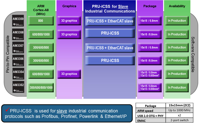
The TI AM335x consists of 6 pin-pin compatible devices
(AM3352, AM3354, AM3356, AM3357, AM3358 and AM3359) with various options
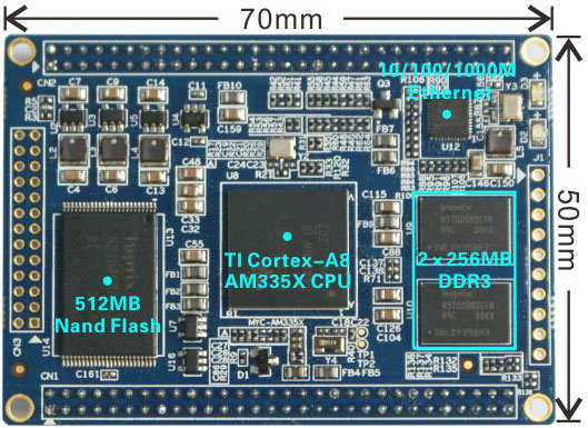
including speed grades, packages, graphics and peripherals. MYIR is using the 15x15 mm, 0.8-mm ball
pitch, ZCZ package AM335x ARM CPU on the MYC-C335X-V4 which is an SOM
(System on Module) and has the core components AM335x processor, 512MB DDR3
SDRAM, 512MB Nand Flash and Gigabit Ethernet PHY chip on board and can be
served as the core of your embedded system. It has two 2.0mm pitch 60-pin male
expansion connectors, one 2.0mm pitch 26-pin interface and one 2.0mm pitch
10-pin interface to allow extension of all the controller signals and ports to the
base board through headers and connectors, thus exposing more features of the
AM335x Cortex-A8 Processors.
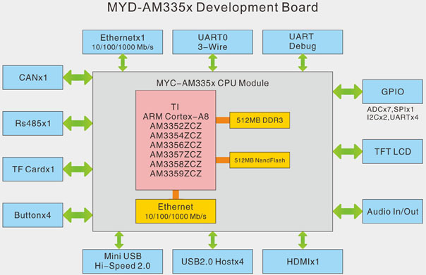
MYC-AM335X CPU Module
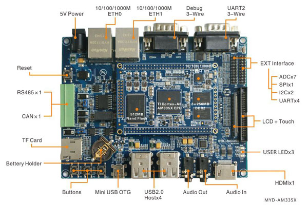
The MYD-C335X-V4 base board has extended many features and peripherals
with the support of the MYC-C335X-V4 SOM and some extended controller chips
including two serial ports, four USB Host ports, one USB OTG port, dual Gigabit
Ethernet ports, one CAN, one RS485, one Micro SD, HDMI, LCD, Touch screen and
more others.
User can integrate a different MYC-C335X-V4 SOM on the same base board,
thus making six variants of AM335x evaluation boards.
The MYD-C335X-V4 series ARM Cortex-A8 boards have
many features in common only with some differences depending on the AM335x
Cortex-A8 CPU features. You can get to know the differences from above image.
The MYD-C335X-V4 board comes with Linux 4.1.18 software packages, detailed documents, necessary cable accessories
as well as optional 4.3- and 7-inch LCD (with touch screen) to provide an
AM335x starter kit and enable a quickly start of evaluation of AM335x Cortex-A8
MPUs.
Features
Mechanical Parameters
-
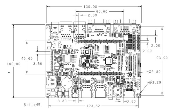
Dimensions: 130mm x 100mm (base board), 70mm x 50mm (SOM)
-
PCB Layers: 4-layer design (base board), 8-layer design (SOM)
-
Power supply: +5V/2A (base board), +3.3V/0.8A (SOM)
-
Working temperature: 0~70 Celsius (commercial grade) or -40~85
Celsius (industrial grade)
The MYD-C335X-V4 Controller Board (MYC-C335X-V4)
Processor
-
TI AM3352, AM3354, AM3356, AM3357, AM3358, AM3359 (15x15 mm, 0.8-mm ball pitch, ZCZ package)
- 800MHz
ARM Cortex-A8 32-bit RISC MPU (Up to 1GHz)
- NEON™ SIMD Coprocessor
- 32KB/32KB of L1 Instruction/Data Cache
with Single-Error Detection (parity)
- 256KB of L2 Cache with Error Correcting
Code (ECC)
- SGX530 Graphics Engine
- Programmable Real-Time Unit Subsystem
Memory
-
512MB (2*256MB) DDR3 SDRAM (2*128MB compatible)
-
512MB Nand Flash (256MB compatible)
Peripherals and Signals Routed to Pins
-
On-board
Gigabit Ethernet PHY
-
One power
indicator (Red LED)
-
One user LED
(Green)
-
Two 2.0mm pitch
60-pin expansion connectors can carry out interfaces below
- 2 x USB2.0 OTG ports
- 6 x Serial ports
- 2 x I2C
- 1 x SPI
- 7 x ADC
- 2 x PWM
- 3 x SDIO
-
One 2.0mm pitch 26-pin expansion connector
-
One 2.0mm pitch 10-pin expansion connector
The MYD-C335X-V4 Base Board
-
Serial ports
- 1 x 3-wire RS232 Debug serial port (DB9)
- 1 x 3-wire RS232 serial port (UART1)
- 1 x RS485 (with isolation)
-
USB
- 4 x USB2.0 Host ports
- 1 x USB2.0 OTG ports
-
2 x 10/100/1000Mbps Ethernet interfaces
-
1 x CAN interface (with isolation)
-
1 x TF card slot
-
1 x HDMI interface
-
1 x LCD interface (16-bit true color, supports optional 4.3-inch and
7-inch TFT LCD with 4.3-inch resistive or 7-inch resistive or 7-inch capacitive touch screen)
-
1 x 4-wire resistive touch screen interface
-
1 x Audio input port (3.5mm jack)
-
1 x Stereo Audio output port (3.5mm jack)
-
4 x Buttons (1 x Reset button, 3 x User buttons)
-
1 x Power indicator (Red LED)
-
2 x
2.0mm 20-pin expansion connectors
- 7 x ADC
- 1 x SPI
- 2 x I2C
- 4 x UART
OS Support
MYD-C335X-V4 in the Video
http://youtu.be/FWbSG2Q-8NM
Other MYIR's TI Products
http://www.myirtech.com/tiseries.asp
Rico Board Single Board Computer (based on AM437x)
MYD-C335X-GW Development Board (MYC-C335X-GW CPU Module as core board, TI AM335x)
MYD-J335X-V2 Development Board (MYC-J335X-V2 as core board, TI AM335x)
MYD-Y335X-V2 Development Board (MYC-Y335X-V2 as core board, TI AM335x)
MYD-YM62X Development Board (MYC-YM62X CPU Module as core board, TI AM6254/6252/6231)
|
Hardware
Specification
The MYD-C335X-V4 series ARM Cortex-A8 boards have many features in common only with some differences depending on the AM335x Cotex-A8 CPU features. You can get to know the differences and more features of the AM335x series processors from below table.
The TI AM335x microprocessors, based on the ARM Cortex-A8, operating at up to 1GHz,
are enhanced with image, graphics processing, peripherals and industrial
interface options such as EtherCAT and PROFIBUS. The device supports the following
high-level operating systems (HLOSs) that are available free of charge from TI:
The AM335x microprocessor
contains these subsystems:
-
Microprocessor unit (MPU)
subsystem based on the ARM Cortex-A8 microprocessor.
-
POWERVR SGX™ Graphics
Accelerator subsystem for 3D graphics acceleration to support display and gaming effects.
-
The Programmable Real-Time
Unit and Industrial Communication Subsystem (PRU-ICSS) is separate from the ARM core, allowing
independent operation and clocking for greater efficiency and flexibility.
-
The PRU-ICSS enables
additional peripheral interfaces and real-time protocols such as EtherCAT, PROFINET, EtherNet/IP, PROFIBUS, Ethernet Powerlink, Sercos, and others.
|
AM335x ARM
Cortex™-A8 Processors
|
|
Core
Feature
|
AM3352
|
AM3354
|
AM3356
|
AM3357
|
AM3358
|
AM3359
|
|
Package
|
15x15mm,
0.8mm (ZCZ)
|
|
CPU
Speed (MHz)
|
300,
600, 800, 1000
|
600,
800,1000
|
300,
600,800
|
300,
600,800
|
600,
800,1000
|
800
|
|
Core
Internal Memory
|
64KB
SRAM shared w/
Data 32KB Cache, Programmable 32KB Cache
|
|
On-chip
L2 (KB)
|
256
|
|
External
Memory Interface
|
DDR2/DDR3/DDR3L/mDDR
(LPDDR), 2x16-bit, NAND ECC
|
|
Graphics
|
-
|
3D
Graphics
|
-
|
3D
Graphics
|
|
OS
Support
|
Linux,
Android, RTOS, Windows Embedded, no-OS
|
|
Other Hardware Acceleration
|
Crypto
Accelerator
|
Crypto
Accelerator
|
2
PRU-ICSS
Crypto Accelerator
|
2
PRU-ICSS
Crypto Accelerator + EtherCAT slave support
|
2
PRU-ICSS
Crypto Accelerator
|
2
PRU-ICSS
Crypto Accelerator
+ EtherCAT slave support
|
|
10/100/1000
EMAC
|
2
port switch
|
|
USB
2.0 OTG + PHY
|
2
|
|
Serial
Ports
|
6
UART, 2 SPI, 3 I2C, 2 McASP, 2 CAN, 8 Timers
|
|
System
|
EDMA,
WDT, RTC, 3 eQEP, 3 eCAP, JTAG, ADC (8ch)
|
|
Parallel
|
3
MMC/SD/SDIO, GPIO
|
Function Block Diagram of MYD-C335X-V4
Dimension Chart of MYD-C335X-V4
|
Software
Features
MYIR’s AM335x Starter Kit MYD-C335X-V4 supports for Linux and is provided with software
packages. Many peripheral drivers are in source code to help accelerate
customers’ designs with a stable and reliable hardware and software platform. The
software features are summarized as below:
|
OS
|
Item
|
Features
|
Description
|
|
Linux
|
Bootstrap program
|
SPL
|
The primary bootstrap
|
|
u-boot
|
The secondary bootstrap
|
|
Kernel
|
Version
|
Linux 4.1.18
|
|
Drivers
|
USB OTG, USB WiFi, Gigabit Ethernet, MMC/SD/TF, NandFlash, CAN, RS485,
Audio, LCD Controller (supports 4.3- and 7-inch LCD), RTC, HDMI, Touch
driver, Button, UART, LED
|
|
File system
|
Buildroot
With QT library (V5.6.2)
|
Provide image file and buildroot in source code
|
|
Examples
|
Audio, CAN, EEPROM, framebuffer, gpio, keypad, led, mtd, network, rtc,
RS232, RS485
|
|
Relative Download and Links
You can download relative chip datasheet, products datasheet, user manual, software package from below. Any inquiry, please contact MYIR.
|
1
|
TI AM335x Datasheet
|
2.80 MB
|

|
|
2
|
TI AM335x Technical Reference Manual
|
19.7 MB
|
|
|
3
|
MYD-C335X-V4 Development Board Overview
|
1.12 MB
|
|
|
4
|
MYC-C335X-V4 Overview
|
1.03 MB
|
|
|
5
|
MYC-C335X-V4 Dimensions
|
844 KB
|
|
|
6
|
MYD-C335X-V4 Development Board Dimensions
|
138 KB
|
|
|
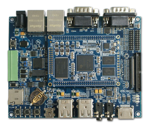
MYD-C335X-V4 Development Board
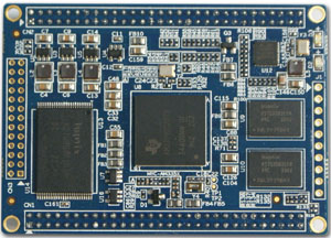
MYC-C335X-V4 Top-view
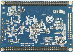
MYC-C335X-V4 Bottom-view
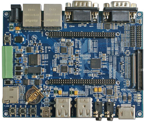
MYD-C335X-V4 Development Board Base Board
|
Price and Ordering
|
Item
|
Part No.
|
Unit Price
|
Ordering
|
|
MYD-C335X-V4 Development Board
(commercial, 512MB DDR3, 512MB Flash)
|
MYD-C3352-V4-512N512D-80-C
|
USD105
|

|
MYD-C3358-V4-512N512D-100-C
|
USD109
|
|
MYD-C335X-V4 Development Board
(industrial, 512MB DDR3, 512MB Flash)
|
MYD-C3352-V4-512N512D-80-I
|
USD129
|
|
MYD-C3358-V4-512N512D-100-I
|
USD135
|
|
MYD-C335X-V4 Development Board
(industrial, 256MB DDR3, 256MB Flash)
|
MYD-C3352-V4-256N256D-80-I
|
USD115
|
|
MYD-C3358-V4-256N256D-100-I
|
USD119
|
|
MYC-C335X-V4
(commercial, 512MB DDR3, 512MB Flash)
|
MYC-C3352-V4-512N512D-80-C
|
USD49
|
|
MYC-C3358-V4-512N512D-100-C
|
USD55
|
|
MYC-C335X-V4
(industrial, 512MB DDR3, 512MB Flash)
|
MYC-C3352-V4-512N512D-80-I
|
USD65
|
|
MYC-C3358-V4-512N512D-100-I
|
USD70
|
|
MYC-C335X-V4
(industrial, 256MB DDR3, 256MB Flash)
|
MYC-C3352-V4-256N256D-80-I
|
USD49
|
|
MYC-C3358-V4-256N256D-100-I
|
USD55
|
|
|
MY-LCD43TP 4.3 inch LCD Module
with resistive touch screen
|
MY-TFT043RV2
|
USD59
|
|
|
MY-LCD70TP 7 inch LCD Module
with resistive touch screen
|
MY-TFT070RV2
|
USD79
|
|
MY-LCD70TP-C 7 inch LCD Module
with capacitive touch screen
|
MY-TFT070CV2
|
USD89
|
|
MY-CAM002U USB Camera Module
|
MY-CAM002U
|
USD19
|
|
MY-WF003U USB WiFi Module
|
MY-WF003U
|
USD13
|
|
|
Note:
1. One MYD-C335X-V4 Development Board includes one MYC-C335X-V4 SOM mounted on the base board by default. If you need more SOMs, please order extra ones.
2 . We deliver the board with 800MHz AM3352 or 1GHz AM3358 by default. If you need other CPU model, RAM or Flash configuration, please contact MYIR for availability.
3. Bulk discounts are available. Please contact MYIR for inquires.
4. The boards of commercial grade can work in temperature ranging from 0~70 Celsius. The boards of industrial grade can work in temperature ranging from -40~85 Celsius. The HDMI chip on board can only work in temperature ranging from -20~70 Celsius.
5. We accept custom design based on the MYD-C335X-V4, whether reducing, adding or modifying the existing hardware according to customer’s requirement.
|
Packing List
|
NO.
|
Item
|
Qty
|
Description
|
|
1
|
MYD-C335X-V4 board
|
1pc
|
MYD-C3352-V4/MYD-C3358-V4
|
|
2
|
Power adapter
|
1pc
|
5V/2A Power adapter
|
|
3
|
Ethernet cable
|
1pc
|
|
|
4
|
USB Cable
|
1pc
|
|
|
5
|
MY-LCD43TP (optional)
|
1pc
|
4.3 inch LCD with resistive touch screen
|
|
6
|
MY-LCD70TP (optional)
|
1pc
|
7 inch LCD with resistive touch screen
|
|
7
|
MY-LCD70TP-C (optional)
|
1pc
|
7 inch LCD with capacitive touch screen
|
|
More FAQ >>
1. How to download kernel and file system through tftp in u-boot?Question:How to download kernel and file system through tftp in u-boot?Answer:
1. Install TFTP on Ubuntu.
2. Please copy the kernel and file system to tftp directory under Ubuntu system, for example, copy uImage and ubi.img to the /tftpboot directory under Ubuntu system.
3. 1) Press “Enter” to get into u-boot command mode when the board start countdown;
2) Configure u-boot environment;
1 set ipaddr 192.168.1.250
2 set ethaddr 88:33:14:f6:c0:d4
3 set serverip 192.168.1.220
4 saveenv
5 reset
The above commands are used for setting IP address of the board, MAC address of the Ethernet, IP address of the Ubuntu Host server, saving variables and restart. Then use ping command to ensure the board pings through with the Host.
1 ping 192.168.1.220
2 Auto negotitation failed
3 link up on port 0, speed 100, full duplex
4 Using cpsw device
5 host 192.168.1.220 is alive
For above, if prompts “host xxx is alive”, it means the board has pinged through with the Host successfully. If failed, it will prompts as below:
1 MYD_AM335X# ping 192.168.1.220
2 Auto negotitation failed
3 Auto negotitation failed
4 Using cpsw device
5 ping failed; host 192.168.1.220 is not alive
3) Acquire Address Assignment
Use printenv to check u-boot environment variables
1 printenv
There will be some output as below:
"updatesys=nand erase.chip;mmc rescan; fatload mmc 0 82000000 MLO;nandecc hw 2;nand write.i 82000000 0 ${filesize}; fatload mmc 0 82000000 u-boot.img;nandecc hw 2;nand write.i 82000000 80000 ${filesize}; fatload mmc 0 82000000 uImage;nandecc hw 2;nand write.i 82000000 280000 ${filesize}; fatload mmc 0 82000000 ubi.img;nandecc sw;nand write.i 82000000 780000 ${filesize};led flash all"
all
The purple part indicates programming MLO; the red part indicates programming u-boot; the green part indicates programming uImage; the blue part indicates programming filesystem, the nandecc hw 2 and the nandecc sw need ECC hardware checking and software checking.
The address assignment is as below:
First boot address: 0x0
RAM memory address: 0x82000000
u-boot address: 0x80000
kernel address: 0x280000
ubi.img
filesystem address: 0x780000
4) Download kernel
Download kernel from PC to the board RAM 0x82000000, the length will be reminded after succeed such as Bytes transferred = 3605768 (370508 hex)
1
2 tftp 0x82000000 uImage
nandecc hw
2 #AM335X kernel needs ecc checking or it will have error: ECC: uncorrectable.
If executing above command, it displays “#”, it means transmitting file; if prompts “TTT…”, it means transmitting overtime, you may need to check if the board has pinged through Host successfully.
Erase the content of 0x370508 byte from 0x280000 address:
1 nand erase 0x280000 0x370508
Write the content of RAM 0x82000000 to Flash address 0x280000, length is 0x3605768:
1 nand write.i 0x82000000 0x280000 0x370508
For above
-
nand write.jffs2 program JFFS2 file system, jump over the bad block
-
nand write.i equal to nand write.jffs2
-
nand write.yaffs program yaffs2 file system, need page aligned
Download file sytem
Download file system from PC to the board RAM 0x82000000, the length will be prompted after downloading successfully, using hexadecimal, command is as below:
1 tftp 0x82000000 ubi.img
2 nandecc sw #AM335X kernel needs ecc software checking
Note: due to the large size of filesystem, please do not interrupt during the filesystem transmitting to avoid failure.
Erase the content of 0x3da000 byte from 0x780000
1 nand erase 0x780000 0x3da0000
Write the content of RAM 0x82000000 to the FLASH 0x780000 with length 0x3da0000:
1 nand write.i 0x82000000 0x780000 0x3da0000
2. ARM Linux GPIO sample codeQuestion:Please download the sample code package from below link:
http://www.myirtech.com/download/code/gpio.tar.gz
(include source code, Makefile and image which is compiled using arm-none-linux-gnueabi-gcc)Answer:
Source code
|
001
002
003
004
005
006
007
008
009
010
011
012
013
014
015
016
017
018
019
020
021
022
023
024
025
026
027
028
029
030
031
032
033
034
035
036
037
038
039
040
041
042
043
044
045
046
047
048
049
050
051
052
053
054
055
056
057
058
059
060
061
062
063
064
065
066
067
068
069
070
071
072
073
074
075
076
077
078
079
080
081
082
083
084
085
086
087
088
089
090
091
092
093
094
095
096
097
098
099
100
101
102
103
104
105
106
107
108
109
110
111
112
113
114
115
116
117
118
119
120
121
122
123
124
125
126
127
128
129
130
131
132
133
134
135
136
137
138
139
140
141
142
143
144
145
146
147
148
149
150
151
152
153
154
155
156
157
158
159
160
161
162
163
164
165
166
167
168
169
170
171
172
173
174
175
176
177
178
179
180
181
182
183
184
185
186
187
188
189
190
191
192
193
194
195
196
197
198
199
200
201
202
203
204
205
206
207
208
209
210
211
212
213
214
215
216
217
218
219
220
221
222
223
224
225
226
227
228
229
230
231
232
233
234
235
236
237
238
239
240
241
242
243
244
245
246
247
248
249
250
251
252
253
254
255
256
257
258
259
260
261
262
263
264
265
266
267
268
269
270
271
272
273
274
275
276
277
278
279
280
281
282
283
284
285
286
|
#include<stdio.h>
#include <stdlib.h>
#include<sys/types.h>
#include<sys/stat.h>
#include<fcntl.h>
#include<unistd.h>
#include<errno.h>
#include<string.h>
#include <poll.h>
#define SYSFS_GPIO_DIR "/sys/class/gpio"
#define GPIO_LED 41
#define MAX_BUF 60
#define POLL_TIMEOUT (3 * 1000) /* 3 seconds */
#define OUT 1
#define IN 0
int gpio_export(unsigned int gpio)
{
int fd ,len;
char buf[MAX_BUF];
fd = open(SYSFS_GPIO_DIR "/export" ,O_WRONLY);
if (fd < 0) {
perror("gpio/export");
return fd;
}
len = snprintf(buf ,sizeof(buf) ,"%d" ,gpio);
write(fd ,buf ,len);
close(fd);
return 0;
}
int gpio_unexport(unsigned int gpio)
{
int fd ,len;
char buf[MAX_BUF];
fd = open(SYSFS_GPIO_DIR "/unexport" ,O_WRONLY);
if (fd < 0) {
perror("gpio/unexport");
return fd;
}
len = snprintf(buf ,sizeof(buf) ,"%d" ,gpio);
write(fd ,buf ,len);
close(fd);
return 0;
}
int gpio_set_dir(unsigned int gpio ,int out_flag)
{
int fd ,len;
char buf[MAX_BUF];
len = snprintf(buf, sizeof(buf), SYSFS_GPIO_DIR "/gpio%d/direction", gpio);
fd = open(buf ,O_WRONLY);
if (fd < 0) {
perror(buf);
return fd;
}
if (out_flag)
write(fd ,"out" ,4);
else
write(fd ,"in" ,3);
close(fd);
return 0;
}
int gpio_set_value(unsigned int gpio, unsigned int value)
{
int fd, len;
char buf[MAX_BUF];
len = snprintf(buf, sizeof(buf), SYSFS_GPIO_DIR "/gpio%d/value", gpio);
fd = open(buf, O_WRONLY);
if (fd < 0) {
perror("gpio/set-value");
return fd;
}
if (value)
write(fd, "1", 2);
else
write(fd, "0", 2);
close(fd);
return 0;
}
int gpio_get_value(unsigned int gpio, unsigned int *value)
{
int fd, len;
char ch;
char buf[MAX_BUF];
len = snprintf(buf ,sizeof(buf), SYSFS_GPIO_DIR "/gpio%d/value" ,gpio);
fd = open(buf ,O_RDONLY);
if (fd < 0) {
perror("gpio_get_value");
return fd;
}
read(fd ,&ch ,1);
if (ch == '1')
*value = 1;
else if(ch == '0')
*value = 0;
close(fd);
return 0;
}
int gpio_set_edge(unsigned int gpio ,char *edge)
{
int fd ,len;
char buf[MAX_BUF];
len = snprintf(buf ,sizeof(buf) ,SYSFS_GPIO_DIR "/gpio%d/edge" ,gpio);
fd = open(buf ,O_WRONLY);
if (fd < 0) {
perror("gpio_set_edge");
return fd;
}
write(fd ,edge ,strlen(edge) + 1);
close(fd);
return 0;
}
int gpio_fd_open(unsigned int gpio)
{
int fd, len;
char buf[MAX_BUF];
len = snprintf(buf, sizeof(buf), SYSFS_GPIO_DIR "/gpio%d/value", gpio);
fd = open(buf, O_RDONLY | O_NONBLOCK );
if (fd < 0) {
perror("gpio/fd_open");
}
return fd;
}
int gpio_fd_close(int fd)
{
return close(fd);
}
int main(int argc, char **argv)
{
struct pollfd *fdset;
int nfds = 1;
int gpio_fd, timeout, rc;
char *buf[MAX_BUF];
unsigned int gpio;
int len;
char *cmd;
unsigned int value;
fdset = (struct pollfd*)malloc(sizeof(struct pollfd));
if (argc < 3) {
printf("Usage: %s <gpio-pin> <direction> [value]\n\n", argv[0]);
exit(-1);
}
cmd = argv[2];
gpio = atoi(argv[1]);
gpio_export(gpio);
if (strcmp(cmd, "interrupt") == 0) {
printf("\n**************************GPIO interrupt***************************\n");
gpio_set_dir(gpio, IN);
gpio_set_edge(gpio, "rising");
gpio_fd = gpio_fd_open(gpio);
timeout = POLL_TIMEOUT;
while (1) {
memset((void*)fdset, 0, sizeof(fdset));
fdset->fd = gpio_fd;
fdset->events = POLLPRI;
rc = poll(fdset, nfds, timeout);
if (rc < 0) {
printf("\npoll() failed!\n");
return -1;
}
if (rc == 0) {
printf(".");
}
if (fdset->revents & POLLPRI) {
len = read(fdset->fd, buf, MAX_BUF);
printf("\nGPIO %d interrupt occurred\n", gpio);
}
fflush(stdout);
}
gpio_fd_close(gpio_fd);
} else if (strcmp(cmd, "out") == 0) {
gpio_set_dir(gpio, OUT);
if (argc = 4) {
gpio_set_value(gpio, atoi(argv[3]));
printf("gpio%d is set to %d\n", gpio, atoi(argv[3]));
}
} else if (strcmp(cmd, "in") == 0) {
gpio_set_dir(gpio, IN);
printf("\n");
while (1) {
gpio_get_value(gpio, &value);
printf("\rvalue:%d", value);
}
} else if (strcmp(cmd, "unexport") == 0) {
gpio_unexport(gpio);
}
else {
printf("Usage: %s <gpio-pin> <direction> [value]\n\n", argv[0]);
exit(-1);
}
return 0;
}
|
Testing
MYD-IMX28X
Execute below command to configure the PD14 to be interruption function on the development board. Use a falling edge trigger for this pin, relative information will be printed out when the program detected the falling edge.
|
1
2
3
4
5
6
7
|
root@freescale ~$ ./gpio 99 interrupt
****************************GPIO interrupt*****************************
GPIO 99 interrupt occurred
.......
GPIO 99 interrupt occurred
|
Execute below command to configure gpio as output and set corresponding values:
|
1
2
3
4
|
root@freescale ~$ ./gpio 99 out 0
gpio99 is set to 0
root@freescale ~$ ./gpio 99 out 1
gpio99 is set to 1
|
Execute below command to configure gpio as input and get input value:
|
1
2
3
|
root@freescale ~$ ./gpio 99 in
value:1
|
Execute below command to export gpio:
|
1
|
root@freescale ~$ ./gpio 99 unexport
|
MYD-AM335X
Execute below command to configure the gpio3_5 pin on the board to be interruption function. Use a falling edge trigger for this pin, it will print out relative information when the program detected the failing edge.
|
1
2
3
4
5
6
7
|
root@MYD-AM335X:~
****************************GPIO interrupt*****************************
GPIO 101 interrupt occurred
....
GPIO 101 interrupt occurred
|
Execute below command to configure gpio as output and set corresponding values:
|
1
2
3
4
|
root@MYD-AM335X:~
gpio101 is set to 0
root@MYD-AM335X:~
gpio101 is set to 1
|
Execute below command to configure gpio as input and get input value:
|
1
2
3
|
root@MYD-AM335X:~
value:0
|
Execute below command to export gpio:
3. How many USB can be used on the MYD-AM335X board?Question:How many USB can be used on the MYD-AM335X board?Answer:
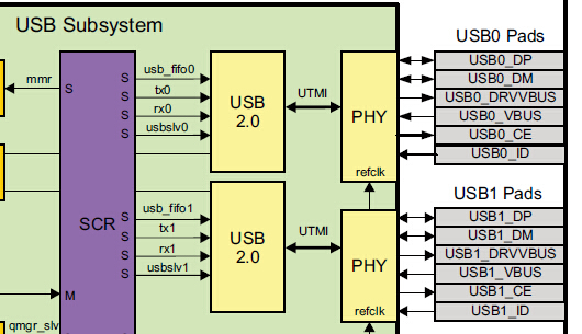
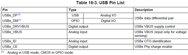
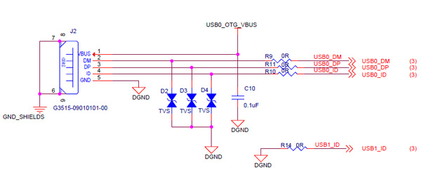
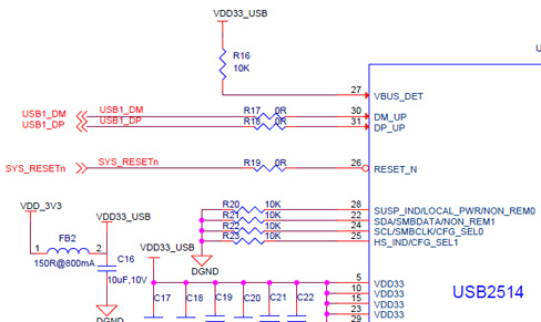
The AM335x CPU has two USB signals: USB0 and USB1. MYIR's MYD-AM335X development board has total 5 USB port including the 1 USB OTG port. We have used USB Hub chip USB2514 on our board to extend USB1 to 4 channels. The USB OTG is connected to the USB0 signal. So there are total 5 USB can be used on the MYD-AM335x board.
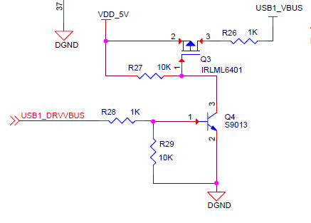
You may don't need so 4 USB Host, you can tailor to your requirement. For example, if you only need to use one USB Host, you need only connect USB to USB1_DM and USB1_DP, plus the USB1_DRVVBUS driver that's OK. The USB1_ID is connected to GND.
AM335x has two USB signals
AM335x USB pin list
MYD-AM335X USB OTG
MYD-AM335X USB Host
MYD-AM335X USB Host driver circuit
4. How to use six serial ports of the MYD-AM335X board in Linux?Question:The MYD-AM335X board has six serial ports. How can I use all the serial ports?Answer:
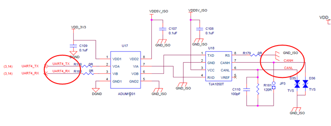
The MYD-AM335X board has six serial ports. But UART4 and UART5 have been reused with other functions. If sometimes you need to use all the six serial ports, we can modify the kernel.
-
The UART4 is reused with CAN, we use CAN by default
-
The UART5 is reused with K2/K3 button, we use K2/K3 button by default.
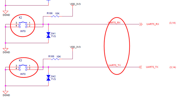
Note: So if you want to use UART4 and UART5, you can not use the CAN and K2/K3 button then.
Please make modifications about kernel as below:
1. Open the kernel file
$vi arch/arm/mach-omap2/board-am335xevm.c
2. Add UART4 and UART5 function definition codes if not exist.
/* Module pin mux for uart3 */
static struct pinmux_config uart3_pin_mux[] = {
{"spi0_cs1.uart3_rxd", OMAP_MUX_MODE1 | AM33XX_PIN_INPUT_PULLUP},
{"ecap0_in_pwm0_out.uart3_txd", OMAP_MUX_MODE1 | AM33XX_PULL_ENBL},
{NULL, 0},
};
/* Module pin mux for uart4 */
static struct pinmux_config uart4_pin_mux[] = {
{"uart0_ctsn.uart4_rxd", OMAP_MUX_MODE1 | AM33XX_PIN_INPUT_PULLUP},
{"uart0_rtsn.uart4_txd", OMAP_MUX_MODE1 | AM33XX_PULL_ENBL},
{NULL, 0},
};
/* Module pin mux for uart5 */
static struct pinmux_config uart5_pin_mux[] = {
{"mii1_col.uart5_rxd", OMAP_MUX_MODE3 | AM33XX_PIN_INPUT_PULLUP},
{"rmii1_refclk.uart5_txd", OMAP_MUX_MODE3 | AM33XX_PULL_ENBL},
{NULL, 0},
3. Add UART initialization code if not exist, as below in blue words.
static void uart3_init(int evm_id, int profile)
{
printk("--------uart3_init\n");
/* Configure Uart3*/
setup_pin_mux(uart3_pin_mux);
return;
}
static void uart4_init(int evm_id, int profile)
{
printk("--------uart4_init\n");
/* Configure Uart4*/
setup_pin_mux(uart4_pin_mux);
return;
}
static void uart5_init(int evm_id, int profile)
{
printk("--------uart5_init\n");
/* Configure Uart4*/
setup_pin_mux(uart5_pin_mux);
return;
}
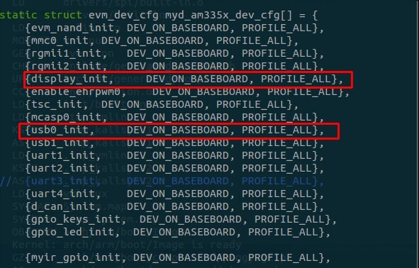
4. Add registration for the UART4 and UART5 and comment out the CAN and keys functions as in below red codes.
{uart1_init, DEV_ON_BASEBOARD, PROFILE_ALL},
{uart2_init, DEV_ON_BASEBOARD, PROFILE_ALL},
{uart3_init, DEV_ON_BASEBOARD, PROFILE_ALL},
{uart4_init, DEV_ON_BASEBOARD, PROFILE_ALL},
{uart5_init, DEV_ON_BASEBOARD, PROFILE_ALL},
// {d_can_init, DEV_ON_BASEBOARD, PROFILE_ALL},
// {gpio_keys_init, DEV_ON_BASEBOARD, PROFILE_ALL},
{gpio_led_init, DEV_ON_BASEBOARD, PROFILE_ALL},
{NULL, 0, 0},
5. Re-compile the kernel and update the system.
5. Troubleshooting TF cardQuestion:When I switch the jumper to run the board from the TF card, the board only outputs " CCCCC" to the terminal screen. What's the problem?Answer:
There are two reasons to cause the problem:
1. You have not used the “HP USB Disk Storage Format Tool 2.0.6.EXE” tool to format the TF card, please use the tool we provided in the product disk under 03-Tools folder;
2. If the TF card has a special write lockout function and was written protected.
6. map_hwmod: wd_timer2: __wait_target_disable failedQuestion:When using the watchdog on MYD-AM335X board, there will appear below error information:
map_hwmod: wd_timer2: __wait_target_disable failed
It doesn't affect the using of watchdog, but it will appear always, how to remove this information?Answer:
We can remove this information through modifying linux-3.2/arch/arm/mach-omap2/omap_hwmod.c
--- linux/arch/arm/mach-omap2/omap_hwmod.c.orig 2012-06-12 16:13:11.166367276 +0200
+++ linux/arch/arm/mach-omap2/omap_hwmod.c 2012-06-12 16:15:56.319482962 +0200
@@ -781,6 +781,8 @@
oh->prcm.omap4.clkctrl_offs);
}
+#define WD_FILTER "wd_timer2"
+
/**
* _omap4_disable_module - enable CLKCTRL modulemode on OMAP4
* @oh: struct omap_hwmod *
@@ -807,10 +809,10 @@
oh->prcm.omap4.clkctrl_offs);
v = _omap4_wait_target_disable(oh);
+ if (strcmp(oh->name, WD_FILTER))
+ pr_warn("omap_hwmod: %s: _wait_target_disable failed\n", oh->name);
+ }
return 0;
}
7. What are the differences for the AM3352, 3354, 3356, 3357, 3358 and 3359 boards?Question:What are the differences for the AM3352, 3354, 3356, 3357, 3358 and 3359 boards?Answer:
MYIR is using the 15x15 mm, 0.8-mm ball pitch, ZCZ package AM335x ARM CPU on the MYC-AM335X CPU Module and the main differences of the MYD-AM335X boards are from the CPU (AM3352, AM3354, AM3356, AM3357, AM3358 and AM3359) features including speed grades, packages, graphics and peripherals. Please refer to the file below:
 AM335x_Devices AM335x_Devices
8. Verifying Checksum ... Bad Data CRCERROR:Question:I have added contents for the kernel and recompile it and the size is much bigger than the former one, I update the image to Nand Flash, all is OK, but the errors display when booting again.
NAND read: device 0 offset 0x280000, size 0x400000 4194304 bytes read: OK
## Booting kernel from Legacy Image at 80007fc0 ...
Image Name: Linux3.2.0 Image Type: ARM Linux Kernel Image (uncompressed) Data Size: 4269392 Bytes = 4.1 MiB Load Address: 80008000 Entry Point: 80008000
Verifying Checksum ... Bad Data CRCERROR:
can't get kernel image! Answer:
Please solve in below way:
Press space key when u-boot in the countdown, stop at the u-boot command line and input two lines of commands:
MYD_AM335X# set nand_img_siz '0x500000'
MYD_AM335X# saveenv
Other commands for reference:
MYD_AM335X# print nand_boot
MYD_AM335X# print nand_img_siz
9. How to load LCD and HDMI driver location in Linux?Question:How to load LCD and HDMI driver location in Linux?Answer:
V6 or before V6 edition of the product disk file system: /etc/init.d/rc file
Or V7 and after that edition of the product disk file system: /etc/init.d/rcS file
10. How to tailor to MYD-AM335X kernel?Question:How to tailor to MYD-AM335X kernel?Answer:
LCD and USB parts, remove or comment out below code:
source code path: arch/arm/mach-omap2/board-am335xevm.c
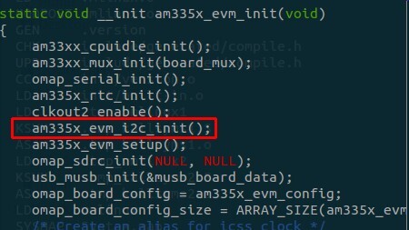
I2C part, remove or comment out below code:
source code path: arch/arm/mach-omap2/board-am335xevm.c
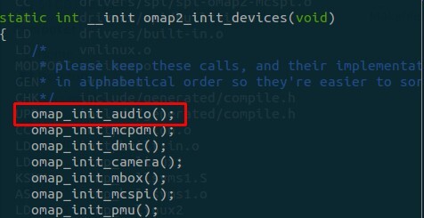
Audio part: remove or comment out below codes in kernel source code
source code path: arch/arm/mach-omap2/devices.c
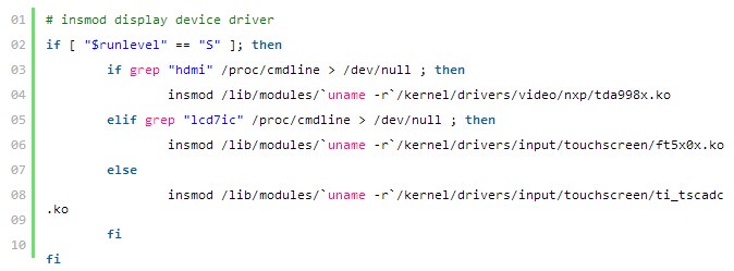
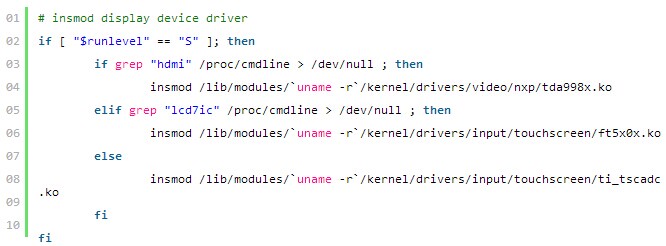
HDMI and touch screen driver
remove or comment out below codes in file system:
script files: /etc/init.d/rc file or /etc/init.d/rcS file
More FAQ >>
|
|
| |
|
|
|
|


 Overview